...Return To Mine & Other Bonneville Car Construction Pages
.Previous Page...............B'ville Car Index Page.........................Next Page
...............................................-- Gas Tank Part I --
.................. .
.
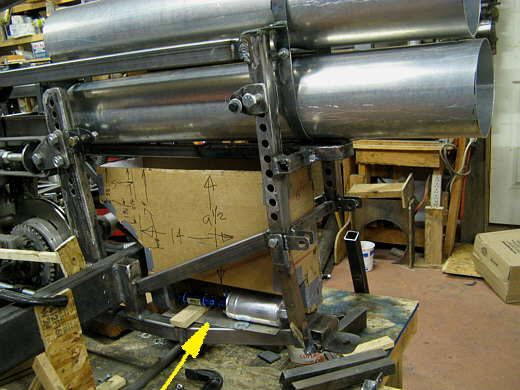
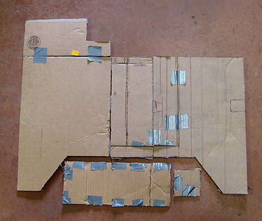
The gas tank is going in an area below the chute tubes and right behind the rear cross-member as shown by the card board mockup. The bar at the back of it is removable and the tank will slide straight out the back of the car. I tried to make the tank as large as this area will allow and had to remember to give clearance on it's sides for the shocks that will be mounted horizontally here. It has a recess for the pre-pump filter and for the pump itself.
.................. .
.
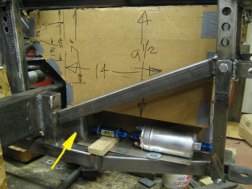
A close up of the filter/pump area. The arrow points to a narrow sump at the bottom of the tank and a -8 AN male bung will be welded to the tank there and a coupler will connect the pre-filter to the bung. The part numbers and where I got these items and most of the items used on the car can be found on "parts I've used on the Lakester page". The supply lines are -8 AN and the return from the regulator is a - 6 AN. Large for this motor, but I'm still trying to set the car up for a turbo 'busa motor in the future.
.................. .
.
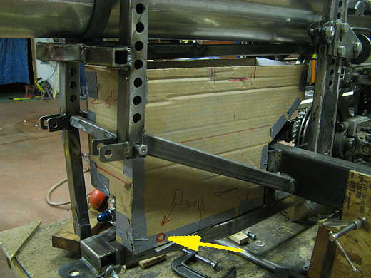
The other side of the tank and the arrow points to were a weld on drain bung will be placed.
.................. .
.
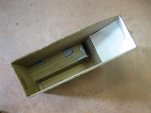
A view down into the tank showing the sump area along the side and back bottom. The tank will also have fuel cell foam installed in it.
.................. .
.
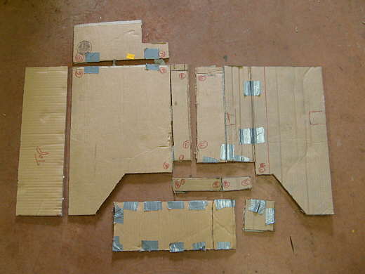
The tape was cut and the tank unfolded. If I had a pan brake and knew how to use it most of the tank could have been cut out of one piece and bent. Since I have a simple press brake .....................................
.................. .
.
............... I cut the cardboard apart into separate pieces that I had the ability to bend. More welding, but that is ok.
.................. .
.
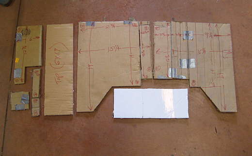
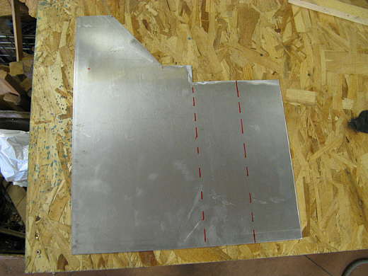
The tank will be made out of .090 5052 aluminum and a left over piece that is 4 ft. X 4 ft. will be used. I laid the parts out so that they would fit across the 4 foot wide piece of aluminum. Notice the dimensions on the pieces. The cardboard is close, but not that accurate.
.................. .
.
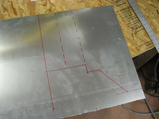
I cut a piece of aluminum off of the 4 X 4 piece 4 feet wide by about 21 inches long. Next the first piece was laid out to the dimensions that had been decided upon. This was done as accurately as possible. The dashed lines are bend lines.
.................. .
.
The piece was cut with the plasma cutter and the edges cleaned up with a small air grinder with those screw on 3M pads.
.................. .
.
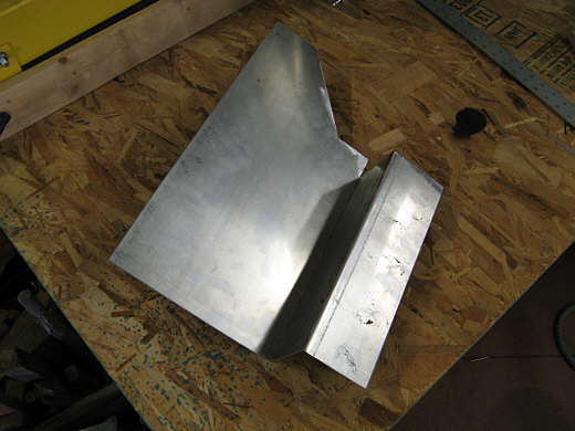
Using the press brake the piece was bent on the fold lines.
.................. .
.
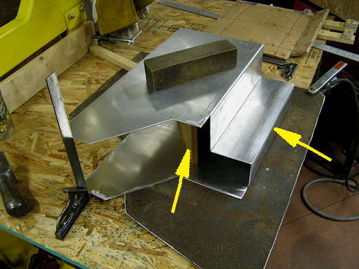
The other side was done in the same manner then they were cleaned with thinner and wire brushed good along the weld seam (right arrow) with a stainless wire brush. I took two pieces of particle board that were cut to 6 inches wide and screwed them together in a "V" shape (left arrow). They held the pieces apart and a weight was put on the top. I used the square to check that the edges were all going to be as square as possible. Not shown was another weight near the weld seam to hold the seam closed while I ....................
.................. .
.
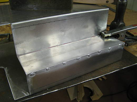
................... tacked the pieces together. I have the weld in bungs on order and don't want to go any further on this until they arrive and I can see how I'm going to deal with them. This tank has cause some worrying, but now that I'm this far I feel pretty good about it maybe coming together.
..............................................................Next Page